Need help with SPI configuration - data is not getting transmitted
sjpatel19922 2017-04-07
Posted on April 07, 2017 at 20:38
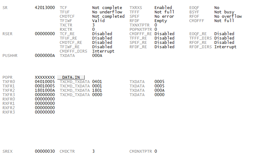
Hello, I would like to know what is wrong with my current configuration of SPI module. I can see data in the TX FIFO, but its not getting transmitted.
I am using the
SPC570S40E1 microcontroller.
SPI Port Configuration
void Initialize_SPI_Port(void)
{
// Using DSPI 0
// DSPI0_CS -- PA[0] , Pin #2, PAD[0]
SIUL2.MSCR_IO[0].B.SSS = PAL_SPC5_SSS(1);
// DSPI0_SCK -- PA[3] , Pin #3, PAD[3]
SIUL2.MSCR_IO[3].B.SSS = PAL_SPC5_SSS(1);
// DSPI0_MISO -- PA[4], Pin #4, PAD[4]
SIUL2.MSCR_IO[4].B.IBE = 1;
SIUL2.MSCR_MUX[624-512].R = PAL_SPC5_SSS(1);
// DSPI0_MOSI -- PA[7], Pin #5, PAD[7]
SIUL2.MSCR_IO[7].B.SSS = PAL_SPC5_SSS(1);
}
??????????????????????????????????????????????????????????????????????????????????????????????????????????????????????????????????
SPI Module conffiguration
void Initialize_DSPI0(void)
{
// Configure DSPI0 Module Configuration Register ( DSPI0_MCR )
// MSTR - 0 , Master mode
// CONT_SCKE - 0 , Continuous SCK disabled
// DCONF - 00 , SPI
// FRZ - 0 , Do not halt serial transfers in debug mode
// MTFE - 0 , Modified Timing Format disabled
// ROOE - 0 , (Receive FIFO Overflow Overwrite) Incoming data is ignored
// PCSIS0 - 1 , Inactive state of PCS0 is high
// MDIS - 1 , Allow external logic to disable DSPI clocks
// DIS_TXF - 0 , TX FIFO enabled
// DIS_RXF - 0 , RX FIFO enabled
// XSPI - 0 , Normal SPI Mode
// FCPCS - 1 , Fast Continuous PCS mode.
// PES - 0 , SPI frame transmission continues
// HALT - 0 , Start transfers
DSPI_0.MCR.R = 0x10004;
// Configure CTAR0 and CTAR1 ( Clock and Transfer Attributes ) Register
// Two transfer attributes used. CTAR0 configured for 16-bit frame size. CTAR1 configured for 8-bit frame size.
// DBR - 0 , Baud rate not doubled
// FMSZ(for CTAR0) - 1111 , Frame size set to FMSZ + 1 or 16 bits
// CPOL - 0 , Clock Polarity - Inactive state value of SCK is low
// CPHA - 0 , Data is captured on the leading edge of SCK and changed on the following edge
// LSBFE - 0 , MSB is transferred first
// PCSSCK - 00 , PCS to SCK Prescaler value is 1
// PASC - 00 , Sets the delay between last SCK edge to negation of CS, 00 sets the Prescaler value to 1
// PDT - 00 , Sets the delay between negation of PCS at end of frame to assertion beginning of next frame, 00 - Prescaler set to 1
// PBR - 00 , Baud Rate Prescaler, set to 2. Available values - 2,3,5, and 7
// CSSCK - 0000 , PCS to SCK Delay Scaler set to 2
// ASC - 0000 , Scaler value for the After SCK Delay, set to 2
// DT - 0000 , Scaler value set to 2
// BR - 0011 , Baud Rate scaler set to 8
/* ------------ Calculation ------------------------
SPI Baud Rate = (Fp / PBR) * ( [1 + DBR]/BR ) , Fp = Peripheral Clock / AC0_DC3 = 64/1 = 64Mhz
= (64/2) * ( [1]/8 )
= 64/16
= 4Mhz
*/
DSPI_0.CTAR[0].R = 0x78000003;
DSPI_0.CTAR[1].R = 0x38000003;
}????????????????????????????????????????????????????????????????????????????????????????????????????????????????????????????????????????????????????????????????????????????????????????????????????????????????????????????????????????????????????????????????????????????????????????????????????????????????????????????????????????????????????????????????????????????????????????????????????????????????
#spc570s #spi
------------------------------
Posted on April 07, 2017 at 22:59
Figured out what the problem was. I didn't realize I had it configured as a slave device.