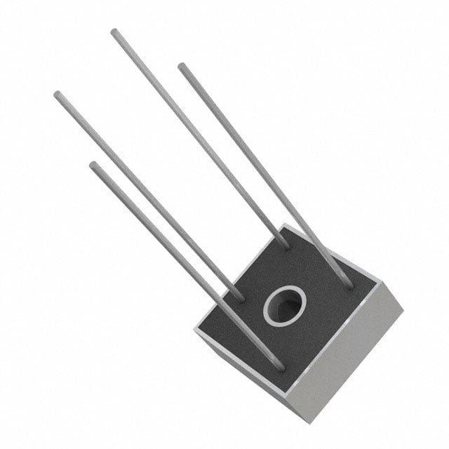
The reverse recovery time (often denoted as (t_{rr})) significantly impacts the performance of a bridge rectifier. Let%27s delve into the details:
1. Definition of Reverse Recovery Time:
- The reverse recovery time refers to the duration it takes for a diode (or rectifier) to transition from the forward-biased state to the reverse-biased state.
- During this transition, the diode momentarily conducts in the reverse direction before effectively stopping current flow.
2. Importance of Reverse Recovery Time:
- Efficiency: A shorter reverse recovery time results in more efficient rectification.
- Switching Losses: Longer recovery times lead to higher switching losses, generating heat and reducing overall efficiency.
- High-Speed Applications: In applications like switched-mode power supplies or circuits requiring rapid rectifier response, minimizing (t_{rr}) is crucial.
- Ideal Switch Behavior: Fast rectifiers approach the behavior of ideal switches, ensuring smooth current flow during switching.
3. Industry Classification:
- Rectifiers are categorized based on their reverse recovery time:
- Fast Rectifiers: Rated with (t_{rr}) of 500 ns or less (approximately one-tenth that of standard rectifiers).
- Ultrafast Rectifiers: Achieve (t_{rr}) of 100 ns or less.
- Small signal diodes (10-100 V) fall within the range of 0.75 to 5 ns for (t_{rr}).
4. Current and Voltage Ratings:
- Ultrafast rectifiers are available in various voltage ratings (from 50 V to 800 V and even up to 1500 V).
- The choice depends on the specific application requirements.
5. Understanding Reverse Recovery:
- When a diode%27s forward current is rapidly switched off (at a high rate of (frac{{di}}{{dt}})), it doesn%27t immediately stop conducting.
- Instead, it briefly reverses its flow, creating a peak overshoot before diminishing to near zero current.
- The anticipated high reverse blocking voltage across the rectifier doesn%27t appear until after the reverse current peak.
6. Application Considerations:
- Catch Diodes: Fast rectifiers serve as protective voltage clamps in parallel with sensitive components (e.g., MOSFETs, IGBTs).
- Heat Management: Efficient rectifiers minimize switching energy losses, reducing heat generation.
- EMC Performance: Ultrafast rectifiers with low (t_{rr}) help meet electromagnetic compatibility (EMC) requirements without additional filters¹²⁴.
In summary, understanding and optimizing reverse recovery time are essential for efficient and reliable bridge rectifier performance in various applications.
(1) Rectifier Reverse Switching Performance - Microsemi. https://www.microsemi.com/document-portal/doc_view/14617-rectifier-reverse-switching-performance.
(2) Rectifier Reverse Switching Performance - Microsemi. https://bing.com/search?q=reverse+recovery+time+bridge+rectifier+performance.
(3) Bridge Rectifiers Improve EMC Performance - EE Times Europe. https://www.eetimes.eu/bridge-rectifiers-improve-emc-performance/.
(4) How Can I Measure the Reverse Recovery Time of Power Rectifiers?. https://www.avtechpulse.com/appnote/techbrief9/.
icDirectory Limited | https://www.icdirectory.com/a/blog/what-is-the-effect-of-reverse-recovery-time-on-bridge-rectifier-performance.html

☰